

Investing in a high-precision bending machine is one of the most critical capital expenditure decisions a sheet metal fabrication facility will make. When sourcing from CNC press brake machine manufacturers in India, buyers frequently encounter a wide spectrum of specifications, structural designs, and price points. However, picking a machine based solely on sticker price or nominal tonnage often leads to recurring production headaches: angular deviations across long parts, excessive hydraulic oil overheating, sluggish cycle times, and frustrating after-sales delays.
A modern Servo Hydraulic Press Brake (commonly known as an electro-hydraulic synchro CNC press brake) bridges the gap between raw hydraulic power and micron-level electronic precision. Whether you are upgrading from conventional torsion-bar machines or expanding an automated precision bending line, making the right choice requires looking deep beneath the sheet metal covers.
This comprehensive technical guide breaks down the structural, hydraulic, electronic, and commercial factors you must audit before signing a purchase order with any Indian machine builder.
What is a Servo Hydraulic Press Brake?
A Servo Hydraulic Press Brake is an advanced CNC bending machine that uses dual independent linear glass scales (Y1 and Y2 axes) paired with high-frequency proportional servo valves to synchronize the left and right hydraulic cylinders in real time. Unlike mechanical torsion-bar machines, it continuously monitors and corrects ram tilt to deliver angular accuracy within
Why Fabricators Are Upgrading from Conventional Hydraulic Systems
Conventional hydraulic press brakes link the two cylinders mechanically via a heavy torsion bar. While robust for general fabrication, torsion-bar machines exhibit distinct operational limitations:
- No Off-Center Bending Capability: Torsion bars cannot compensate for asymmetric loads. Off-center bending twists the bar, causing rapid seal wear and angular variance.
- Open-Loop Positioning: Mechanical stops inside the cylinders dictate bottom dead center (BDC). Over time, thermal expansion of hydraulic oil changes the BDC position.
- Energy Inefficiency: Standard fixed-displacement induction motors pump hydraulic oil continuously at peak pressure, dumping unspent energy as heat into the reservoir.
In contrast, an electro-hydraulic servo synchro press brake uses closed-loop proportional hydraulics. The CNC controller calculates the precise pressure and oil volume required for the programmed material thickness and V-die opening, keeping the oil cool, reducing power draw by up to 30% to 50%, and enabling multi-station off-center bending.
Technical Comparison: Servo Hydraulic vs. Conventional Hydraulic Press Brakes
|
Feature / Parameter |
Conventional Torsion-Bar Hydraulic |
Servo Hydraulic (Electro-Hydraulic Synchro) |
Practical Shop-Floor Impact |
|
Y1 / Y2 Synchronization |
Mechanical torsion bar |
Independent closed-loop proportional servo valves |
Eliminates ram tilt; enables off-center progressive tooling setups. |
|
Ram Repeatability |
$\pm 0.05\text{ mm}$ to $\pm 0.10\text{ mm}$ |
$\pm 0.005\text{ mm}$ to $\pm 0.01\text{ mm}$ |
Delivers first-part-right bending without trial-and-error shimming. |
|
Bending Angle Accuracy |
$\pm 1.0^\circ$ to $\pm 1.5^\circ$ across 3 meters |
$\pm 0.3^\circ$ to $\pm 0.5^\circ$ across full bed length |
Drastically reduces downstream rework during robotic or manual welding. |
|
Energy Consumption |
Continuous maximum power draw |
On-demand flow control / Variable servo motor drive |
30% to 50% lower electricity bills on typical 2-shift operations. |
|
Bending Speeds |
Fixed single/dual speed |
Programmable fast approach, pressing, and decompression speeds |
Increases output by 20% to 35% on high-volume production runs. |
|
Crowning Compensation |
Manual mechanical shimming |
CNC-controlled dynamic hydraulic or mechanical crowning |
Eliminates the “canoe effect” (over-bent ends, under-bent center). |
|
Oil Degradation & Heating |
High heat build-up; frequent oil changes |
Low operating oil temperatures; extended seal and valve life |
Lowers annual maintenance expenses and prevents mid-day angle drift. |
7 Critical Factors to Check When Evaluating Indian Press Brake Manufacturers
When assessing any CNC press brake manufacturer in India, verify their engineering methodologies, component supply chains, and build quality.
1. Frame Rigidity, Plate Quality, and Stress Relieving
The structural backbone of any press brake is its side housings, bed, and ram. Under load, every press brake frame deflects. High-grade builders design frames with heavy-duty structural steel plates (IS 2062 Grade E250/E350 or equivalent) to keep deflection within strictly defined limits.
- Audit the Stress-Relieving Process: Ask whether the welded frame undergoes thermal furnace annealing or certified vibratory stress relieving before machining. Unrelieved frames warp gradually over 12 to 24 months, permanently misaligning the guide ways.
- Single-Setup Bed Machining: Ensure that the frame side housings and bed guide ways are machined in a single setup on a large CNC floor-type boring machine. This guarantees parallelism between the ram guides and the bed.
2. CNC Controller Ecosystem and Software Interface
The controller serves as the machine’s brain. Top CNC press brake machine suppliers in India partner with globally proven controller brands like Delem (Netherlands), ESA (Italy), or Cybelec (Switzerland).
- Offline Programming: Verify if the machine package includes offline PC software (e.g., Delem Profile-T, ESA Bend). Offline programming allows draftsmen to unfold 3D STEP files, calculate bend deductions, simulate collision detection, and send NC programs directly to the shop floor without halting machine production.
- User Interface: Ensure the touch screen supports intuitive graphical profile drawing so operators can adjust bend sequences on the fly.
3. Sourcing of Hydraulic Servo Valves and Feedback Scales
A machine is only as dependable as its core hydraulic and optical components. Request a written bill of materials (BOM) identifying the exact Tier-1 brands used:
- Proportional Valves: Bosch Rexroth (Germany) or Hoerbiger (Germany).
- High-Pressure Pumps: Voith, Nachi, or Rexroth internal gear pumps.
- Linear Optical Scales: Givi Misure (Italy), Heidenhain (Germany), or Fagor (Spain) with optical resolutions down to $0.001\text{ mm}$ or $0.005\text{ mm}$.
- Hydraulic Connectors & Piping: DIN-standard flared and bite-type seamless cold-drawn tubes with zero-leak elastomeric seals.
Expert Tip: Beware of low-cost machines utilizing unbranded manifold blocks or repurposed industrial solenoids instead of dedicated high-response proportional directional valves. Unstable hydraulics lead to hunting (vibration at the pinch point) and inconsistent bend depths.
4. Backgauge Kinematics and Multi-Axis Configuration
The backgauge determines your cycle speed, repeatability, and ability to handle complex stepped flanges. Inspect the drive mechanisms: ball screws must be ground/precision-rolled (C5 or C7 accuracy classes) riding on dual linear motion guide rails, driven by AC brushless servo motors.
Axis Classifications:
- $X$-Axis: Forward and backward movement (flange length).
- $R$-Axis: Vertical movement (accommodates varying bottom die heights).
- $Z1 / Z2$-Axes: Independent lateral movement of backgauge fingers along the bed length.
- $X1 / X2$ or $X’$: Independent depth travel for tapered or conical bending.
- Finger Stop Design: Look for multi-level backgauge fingers fitted with hardened contact tips, spring-loaded flip-up stops, and LED work-zone lighting.
5. Dynamic Mechanical vs. Hydraulic CNC Crowning
When bending thick or long sheets, the center of the upper ram pushes upward while the center of the lower bed sags downward due to natural physics. Without compensation, parts end up with an open angle in the center.
- CNC Mechanical Crowning (Wedge-Type): Uses a set of precision opposing bi-directional alloy steel wedges positioned beneath the bottom die table. A dedicated servomotor adjusts the wedge profile along the entire length based on calculated CNC bending forces.
- Hydraulic Crowning: Uses multiple hydraulic cylinders embedded inside the lower bed to exert upward pressure.
Recommendation: Mechanical wedge crowning provides higher dynamic stiffness, independent segment fine-tuning, and zero susceptibility to thermal oil variance over long production shifts.
6. Tooling Clamping Systems and Bed Hardness
Tool changeover time directly determines your machine uptime.
- Clamping Options: Evaluate whether the machine features manual European-style fast-clamp levers, hydraulic power clamping, or pneumatic systems (Wila style).
- Bed Hardening: Verify that the intermediate adaptors and lower table surface are induction-hardened to $48\text{–}52\text{ HRC}$. Soft bed tables deform over years of high-tonnage point loads, permanently destroying bending accuracy.
7. Local Service Network, Spares Inventory, and Commissioning
Even the best machine is a liability if a blown seal or electronic drive failure halts production for weeks.
- Local Field Service Engineers: Does the manufacturer have direct regional service centers in key industrial corridors (e.g., Ahmedabad, Pune, Chennai, Delhi NCR, Bengaluru, Hyderabad) and international hubs (such as Dubai, Riyadh, or Johannesburg)?
- Spare Parts Availability: Confirm that electronic modules, proportional valve replacement coils, seals, and linear encoders are stocked locally for dispatch within 24 to 48 hours.
Commercial Investigation: How to Choose the Right Machine for Your Plant
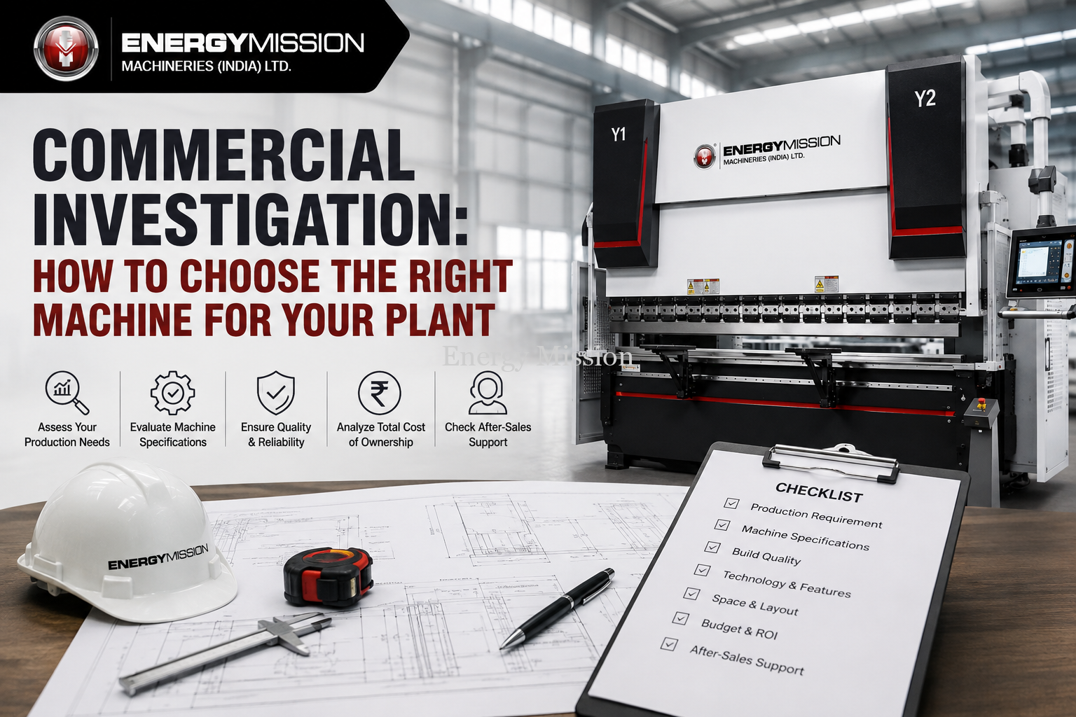
Choosing the correct capacity ensures you don’t overpay for unused tonnage or prematurely stress your frame on heavy jobs.
1. Calculating Tonnage (Air Bending Rule of Thumb)
For mild steel ($\text{Tensile Strength } \sigma_b \approx 450\text{ N/mm}^2$), bending tonnage per meter ($F$) is calculated via the standard air bending formula:
$$F = \frac{1.42 \times \sigma_b \times S^2 \times L}{V \times 1000}$$
Where:
- $S$ = Sheet thickness (mm)
- $L$ = Bending length (mm)
- $V$ = Bottom V-die opening width (mm) — Standard recommendation: $V = 8 \times S$ for sheets up to 6 mm; $V = 10 \times S$ for sheets above 6 mm.
Rule of Thumb: Always add a 20% to 25% safety margin over calculated theoretical tonnage to account for material tensile variations (e.g., switching to SS304 or high-yield Hardox/Weldox grades), bottoming processes, and tool wear.
2. Matching Stroke Length, Open Height (Daylight), and Throat Depth
- Open Height (Daylight): If you manufacture deep electrical enclosures, control panels, or architectural trays, you need deep upper tooling and tall gooseneck punches. Ensure your daylight is at least $450\text{–}550\text{ mm}$ to allow part clearance without crashing into the ram.
- Throat Depth: The depth of the side frame cutouts dictates how wide a return flange you can bend along the full machine width. Standard throat depths range from $320\text{ mm}$ to $500\text{ mm}$ on heavy machines.
Real-World Case Study: Resolving Angular Drift on 3.2-Meter Stainless Steel Bends
A Tier-1 HVAC panel manufacturer in Gujarat was operating two 160-ton conventional mechanical torsion-bar press brakes. They faced high rejection rates on 1.5 mm and 2.0 mm SS304 duct casings.
- The Problem: The bend angle measured $90^\circ$ at both ends but flared open to $92.5^\circ$ in the middle. Operators spent 15–20 minutes per setup hand-shimming the bottom die with paper tape and metal strips. Mid-shift hydraulic oil heating caused an additional $1.0^\circ$ angle drift.
- The Solution: The plant replaced the line with an Energy Mission 170-Ton $\times$ 3100 mm 4+1 Axis Servo Hydraulic Press Brake equipped with a Delem DA-58Tx controller, optical linear scales, and dynamic CNC mechanical crowning.
- The Result:
- Hand-shimming was completely eliminated.
- Angular variation along the entire 3.2-meter length dropped to within $\pm0.3^\circ$.
- Setup times dropped from 25 minutes to under 3 minutes per batch.
- Monthly electricity consumption dropped by 38% due to the on-demand hydraulic pump control.
Preventive Maintenance & Longevity Checklist
To ensure your CNC bending machine delivers micron-level repeatability across a 10- to 15-year operational lifecycle, establish a structured preventive maintenance routine:
Frequently Asked Questions (FAQs)
1. What is the practical difference between an NC Press Brake and a CNC Servo Hydraulic Press Brake?
An NC (Numerically Controlled) press brake uses a basic motorized mechanical stop inside the cylinders (often driven by a single-axis controller) to limit stroke depth. A CNC Servo Hydraulic Press Brake features independent electro-hydraulic proportional valves for each cylinder (Y1/Y2), real-time optical scale feedback, automated bending angle calculations, multi-axis backgauges, and dynamic crowning compensation.
2. Can a Servo Hydraulic Press Brake perform off-center bending without damaging the machine?
Yes. Because the left (Y1) and right (Y2) cylinders are controlled by independent proportional valves reading real-time position from linear glass scales, the CNC controller constantly balances uneven forces. You can perform staged tooling operations (progressive bending) across different sections of the bed without twisting the frame.
3. How much energy does a Servo Hydraulic Press Brake save compared to a standard hydraulic press brake?
Depending on duty cycle and idle time, servo-hydraulic systems save between 30% and 50% on electrical power. Traditional hydraulic machines run large induction motors continuously at full RPM, whereas servo-driven systems throttle motor speed and pump displacement during idle, positioning, and decompression phases.
4. Which CNC controller is ideal for general sheet metal fabrication?
For standard 3+1 or 4+1 axis applications (Y1, Y2, X, R + Crowning), 2D graphical controllers like the Delem DA-53Tx or DA-58Tx and ESA S630 are industry standards. For complex 3D CAD/CAM integration, high-axis counts (6+1 or 8+1 axes), and offline robotic bending cell simulation, advanced controllers like the Delem DA-66T / DA-69T or ESA S660W are recommended.
5. Why is mechanical wedge crowning preferred over hydraulic crowning?
Mechanical wedge crowning provides precise, mathematically mapped counter-curves using opposing metal wedges driven by a high-resolution servo motor. It offers higher rigidity under cyclic loads, allows localized mechanical micro-adjustment at specific points across the bed, and remains unaffected by hydraulic oil temperature fluctuations.
6. What thickness tolerances should I maintain when air bending?
Air bending relies strictly on punch penetration into the V-die opening. A material thickness variance of just $0.1\text{ mm}$ in cold-rolled steel can alter the final bend angle by $0.5^\circ$ to $1.0^\circ$. A high-precision servo hydraulic machine allows micro-stepping depth overrides in the CNC controller ($0.01\text{ mm}$ steps) to instantly correct for sheet batch variations.
7. How often does the hydraulic oil need replacement in a servo hydraulic press brake?
Under normal two-shift operations ($16\text{ hours/day}$), high-grade anti-wear hydraulic oil (ISO VG 46 or 68) should be sampled every 6 months and completely replaced every 4,000 to 5,000 operational hours or every 2 years. Ensure return-line filtration elements (10-micron rating) are replaced annually.
Key Takeaways for Machine Sourcing
- Insist on Independent Y1/Y2 Synchro: Never compromise on closed-loop proportional valve synchronization with optical linear scale feedback.
- Audit Frame Metallurgy: Verify furnace stress-relieving and single-setup floor boring to prevent long-term frame warpage.
- Prioritize Tier-1 European/Japanese Hydraulics: Demand genuine Bosch Rexroth/Hoerbiger valves and Voith/Nachi internal gear pumps.
- Select the Right Crowning System: CNC dynamic mechanical crowning is superior for long-bed, high-tonnage consistency.
- Size with Real Margins: Always factor in material tensile strength variations and maintain a 20–25% tonnage reserve.
- Ensure Local Spares & Support: Partner with manufacturers that provide localized field service, fast spares dispatch, and full application training.
Partner with India’s Leading Press Brake Manufacturer
For more than 25 years, Energy Mission Machineries (India) Ltd. has been at the forefront of designing and manufacturing heavy-duty, high-precision sheet metal fabrication equipment. As a trusted CNC press brake manufacturer in India, Energy Mission engineers robust, reliable machines tailored to demanding production environments.
Our comprehensive manufacturing portfolio includes:
- High-Precision CNC Press Brake Machines (Electro-Hydraulic Servo Synchro, 40 Tons to 1000+ Tons)
- Heavy-Duty Hydraulic Press Brake Machines
- High-Speed CNC Shearing Machines
- 3-Roll & 4-Roll Plate Rolling Machines
- Multi-Function Ironworker Machines & Busbar Processing Machines
Serving leading industrial fabricators across India, the Middle East (UAE, Saudi Arabia, Oman, Qatar, Bahrain, Kuwait), Africa, and the Americas, Energy Mission delivers end-to-end engineering support—from initial component bend simulations and customized multi-axis backgauges to on-site commissioning and operator training.
Planning to upgrade your sheet metal fabrication line?
Contact the Energy Mission Technical Team today for an application-specific tonnage evaluation, machine selection matrix, or custom price quotation.